Heat Shrink Tubing Size Chart: Supplied ID, Recovered ID and Shrink Ratio
Engineer's Guide · 2026-07-24
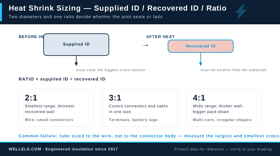
Most heat-shrink failures come from sizing, not material. The tube was either too small to slide over the connector, too large to grip the wire after shrinking, or cut so tight that longitudinal shrink left the conductor exposed. All of that is avoidable by reading the datasheet correctly.
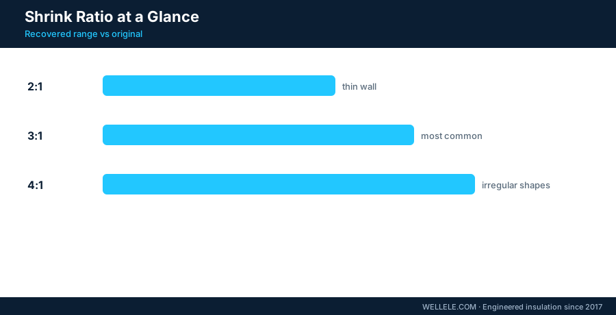
The three numbers on every datasheet
- Supplied ID, the inner diameter before heating. It must clear the largest cross-section of the object you slide it over, including connector bodies, solder bumps and burrs.
- Recovered ID, the inner diameter after full shrink. It must be smaller than the smallest cross-section of the substrate, or the tube will sit loose and provide no grip.
- Shrink ratio, supplied ID divided by recovered ID (2:1, 3:1, 4:1). It expresses how much diameter range one size covers.
How to measure the object correctly
Measure with calipers at the widest point of the assembly, on a terminated wire, that is usually the connector or ferrule, not the conductor. Add working margin of roughly 10 percent on the supplied side, because the object is rarely a perfect circle and the tube has to slide past it. For the recovered side, do not size to the wire if a connector is present; the tube must grip the larger part.
Ratio selection
| Ratio | What it covers | Typical use |
|---|---|---|
| 2:1 | Small diameter difference (wire to wire) | Splicing, bundling, general insulation |
| 3:1 | Moderate difference (wire to terminal) | Terminated wires, cable ends |
| 4:1 | Large difference (connector to thin cable) | Connector backshells, irregular parts |
A higher ratio covers more size range per SKU, which is why 3:1 and 4:1 simplify stock. The tradeoff is slightly thicker recovered walls and a higher price per meter.
Wall thickness and voltage
Datasheets list wall as thin, medium, heavy or dual-wall. Thin-wall tubing is flexible and cheap, for low-voltage insulation. Heavy-wall and dual-wall add dielectric strength and mechanical protection, for busbar, power cable and outdoor joints. As a rule of thumb the recovered wall should scale with voltage class, do not use a 0.3 mm wall where the specification calls for 0.8 mm just because the diameter fits.
Common sizing mistakes
- Sizing to the wire instead of the connector, the tube jams halfway
- Oversizing so the recovered ID never grips, the tube slides and chafes
- Forgetting longitudinal shrink: cut 5-10 percent longer than the splice, or the ends pull back and expose the joint
- Ignoring that a kinked or oval substrate needs more margin than a round one
Worked example
| Object | Value |
|---|---|
| Wire | 2.5 sq mm, 3.2 mm OD |
| Terminal | 6.3 mm max width |
| Required supplied ID | 7.0 mm (6.3 + margin) |
| Required recovered ID | Under 3.2 mm |
| Size chosen | 3:1 tube, 7.4 mm supplied / 2.4 mm recovered |
That single SKU covers the whole assembly. If you have a mixed harness, standardize on 3:1 across three or four sizes and the stock list shrinks fast.
For larger conductors and flat busbar, sizing works the same way but the cross-section is rectangular; our guide to busbar sleeve sizing covers the corner-radius and stack-up calculation separately. For voltage-rated power-cable work, see shrink ratio and voltage rating for power cables.
Specifying this part?
Send the drawing for a manufacturability review.